Thursday, June 26, 2008

Monitor Mix on LS9

How do I setup my LS9 as a monitor console? Where is monitor output and a monitor level master fader?

This is similar to the setup for M7CL but some different features are available on your LS9.

1. TO PATCH MONITOR OUT (p.146 LS9 Owner's Manual)
The default patch does not include an XLR output for cue/monitor signals. To patch the monitor bus to an omni out;

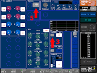
1. In the DISPLAY ACCESS section, press the [MONITOR] key repeatedly to access the MONITOR screen.
2. Move the cursor to the port select box L located below the L level meter, and press the [ENTER] key.
3. Chose your output (OMNI 1 for example) and close the OUTPUT PORT SELECT popup window.
4. If you want to monitor in mono turn the MONO MONITOR button on to combine signals from ST IN channels and hear signals panned to the right.
5. If you want to monitor in stereo repeat steps 2-3 for the R side.

2. CUE LEVEL ON A FADER

Some stage monitor engineers like to have fader control of their Cue listening level.
LS9 has two ways to have the level control on a fader.

With the custom fader layer (p.92 LS9 Owner's Manual):

1. In the DISPLAY ACCESS section, press the [SETUP] key repeatedly to access the USER SETUP screen.
2. Move the cursor to the CUSTOM FADER LAYER popup button in the screen, and press the [ENTER] key.
3. Move the cursor to the channel module select field ("32" for example), use the dial or the [DEC]/[INC] keys to select the MONITOR to that field, and press the [ENTER] key.
4. Press the LAYER [CUSTOM FADER] key in the LAYER section to recall the custom fader layer you’ve created.
5. The fader 32 is now a level control for the Monitor/Cue output.

With the user defined key (p.196 LS9 Owner's Manual):

1. In the DISPLAY ACCESS section, press the [SETUP] key repeatedly to access the USER SETUP screen.
2. Move the cursor to the USER DEFINED KEYS popup button, and press the [ENTER] key.
3. Move the cursor to the button for the user defined key whose function you want to assign ("11" for example), and press the [ENTER] key.
4. Select MONITOR for the function and MASTER FADER for the parameter 1.
5. Press the user defined key 11 to turn the mode on and use the master fader to control the monitor level, and the ON key to switch the monitor output on/off. (LED=lit: Monitor level, LED=dark: Stereo/Mix Master)

3. MIX CUE AND MIX MASTER LEVEL CONTROL
When the SENDS ON FADER mode is activated, the master fader and the ON key control the related Mix master level and on/off. Also the CUE key engages the Mix master to the Cue bus.

Note
The Monitor Master fader mode with the user defined key has priority over assigning function to the master fader by the SENDS ON FADER. For that reason, the master fader assigned to Monitor Master fader mode stays as is even if SENDS ON FADER mode is activated.

Wednesday, June 25, 2008

Pan the input to the stereo Mixes

How do I pan the input signal to send to the stereo Mixes?

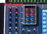
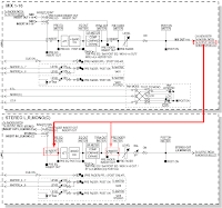
(PM1D, PM5D, M7CL, and LS9) At the Selected Channel area, Mix Send controls for the stereo Mixes are "Pan" (odd) and "Level" (even).

(PM5D V2) When "FLIP" mode is engaged to the input faders and "PAN" key at the encoder mode is pressed, the Channel Encoders are pan controls for the stereo Mixes from the input channels.

The function assigned to the controls in the mode: (Owner's Manual p.49)
Encoder -- Pan of the signal sent from channels (of the currently selected layer) to paired MIX buses (invalid if MIX channels are not paired)
ENCODER [ON] key -- Channel (currently selected layer) on/off
Fader -- Send level from channel (currently selected layer) to MIX bus
CH [ON] key -- On/off status of signal sent from channel (currently selected layer) to MIX bus

(DM/0): It will be set only with the screen.

Tuesday, June 24, 2008

Flattening PEQ

Is there a short-cut for flattening PEQ?

With the following short-cuts, gain parameter will be set to 0dB and its frequency and Q value will stay as is.

(PM1D) Please use a [FLAT] button in the EQ screen. (no hardware short-cut)

(PM5D) Press and hold down UPPER and LOWER keys.

(M7CL) Press both GAIN and Q knobs of a band that you'd like to flatten.

(LS9) Press both HIGH and LOW keys.

(DM2000 and 02r96) Press and hold down FREQUENCY/Q knob of a band that you'd like to flatten.
(DM1000 and 01v96) Press and hold down band key that you'd like to flatten.

Monday, June 23, 2008

Monitor Mix on M7CL

How do I setup my M7CL as a monitor console? Where is monitor output and a monitor level master fader?

Please refer to M7CL Short-cut list.
The following is from the document.

1. TO PATCH MONITOR OUT
The default patch does not include an XLR output for cue/monitor signals. To patch the monitor bus to an omni out;
1. Press the Headphone Icon in the function access panel.
2. Open the MONITOR pop-up by pressing the grey tab to the left of the screen.
3. Press the grey square under the L meter to see the OUTPUT PORT SELECT for Monitor L pop-up and chose your output (OMNI 1 for example).
4. If you want to monitor in mono press MONO MONITOR to combine signals from ST IN channels and hear signals panned to the right.
5. If you want to monitor in stereo repeat steps 1-3 for the R side.

2. CUE LEVEL ON A FADER
Some stage monitor engineers like to have fader control of their Cue listening level. There is no software short-cut for doing this and to achieve this you need a MY card (eg MY8-AE) and break-out cable. Here is a way to configure this on M7CL:
1. In the MONITOR screen MONITOR pop-up, patch the
Monitor out L and R to a Slot outputs, eg Slot 1-1 and Slot 1-2.
2. Physically connect Slot 1-1 output to Slot 1-1 input and Slot 1-2 output to Slot 1-2 input using your breakout cable.
3. Patch the Insert return of the STEREO Master to Slot 1-1 and Slot 1-2. (Select STEREO> “push-click” any encoder> touch INSERT grey square.)
4. Switch on the INSERT for the STEREO masters, and check the INSERT POINT is PRE ATT if you want to use channel EQ.
5. Connect the wedge amp or in-ear pack to OMNI 15(L) and OMNI 16(R) in the default routing or patch the STEREO outputs to your chosen output.
NOTE
Do not cue the STEREO channel, or a feedback loop will be created.
Remember to set the MONITOR LEVEL rotary knob to 10 as the audio still passes through this.

CUE LEVEL ON FADER; AN ALTERNATIVE
If you don’t have access to a suitable MY card you can patch the monitor output to an OMNI out and then bring that back into a spare input channel routed to the MONO master. However remember that this “economy method” introduces an extra DA and AD conversion and routes the signal through an unnecessary HA stage so there will be quality and latency issues that could effect precise monitoring.
NOTE
If you want to use this method for stereo monitoring using the STEREO master fader remember you must unassign all the input channels routed to the STEREO by default.

Thursday, June 19, 2008

PM5DEX is now released

At InfoComm08, Yamaha introduced PM5DEX.
We gave a new name for a system of PM5D and DSP5D.

Also a booklet about PM5D V2 features is available from the web site. I believe most of PM5D are already updated to V2.20 and you are using those functions. But please check it and get better ideas of Virtual Soundcheck function, new security functions, improvements for operations of the system.

Friday, June 13, 2008

PC software for AD8HR remote

ES-Monitor and DME Designer can control AD8HR/AD824 HA Gain from your PC. But it need EtherSound device or DME to do it.

Audio Service has a program for it. "Remotesoftware for Yamaha AD8HR/AD824"
This could be another option for this.

DME frimware V3.09 released

DME got firmware update to V3.09.
This is compatible with DME Designer V3.0.0 or later.

New Features

  • The PM5D console can now communicate with the group master DME whose ID is not limited to only 2 but also allows other numbers, when remotely controlling the DME units from the PM5D (DME Control function). In this case, however, the PM5D firmware must be V2.20 or later.
  • The screen image appearing when the DME64N/24N starts up can now be replaced with a graphic file of your choice in the following way. This function allows you to display a desired startup screen-for example, one that includes your facility's name and logo.

    Preparing the graphic data
    Create the desired graphic data at a size of 160 x 48 dots in black-and-white bitmap format (extension .bmp) and save it as a file with the name "opening.bmp."

    Replacing the graphic data
    Transmit the graphic file ("opening.bmp") to the DME unit using the DME File Storage function from the DME Designer. This image will be displayed at the startup screen from the next time when the DME starts up.

    Other information
    To restore the default startup screen, create a dummy file and change the name to "blank.bmp." and storage it in the same way as above. The default startup screen will be displayed from the next time when the DME starts up.
    The file transmitted to the DME unit using the DME File Storage function will be automatically erased after completing the internal configuration. This means the file is not stored on the DME unit.
    Compatible graphic files are limited to black-and-white bitmap format at a size of 160 x 48. Other graphic files cannot be displayed.
    The "Copyright" indication at the bottom of the screen cannot be erased.
    Only the DME64N/24N is compatible with this function. The ICP1 is incompatible.

Thursday, June 5, 2008

Mono Fader as Mix16 Master Fader

I'm using MIX16 as sub woofer send. Can I use MONO fader for its master level control?

A similar trick as "CUE LEVEL ON A FADER" on page 5 of M7CL Short-Cut List can be used.

There is no software short-cut for doing this and to achieve this you need a MY card (eg MY8-AE installed to Slot 1) and break-out cable. (This gives you input delay, too!)
Here is a way to configure this on M7CL:

1. In the Selected Channel screen of MIX16, patch the MIX16 output to a Slot outputs, eg Slot 1-1. (Select MIX16> “push-click” any encoder> touch PATCH grey square.)

2. Physically connect Slot 1-1 output to Slot 1-1 input using your breakout cable.

3. Patch the Insert return of the MONO Master to Slot 1-1 (Select MONO> “push-click” any encoder> touch INSERT grey square.)

4. Switch on the INSERT for the MONO masters, and check the INSERT POINT is PRE ATT if you want to use both of the channel EQ on MIX16 and MONO.

5. Patch the Output port of the MONO Master to OMNI14 (Select MONO> “push-click” any encoder> touch INSERT grey square.)

6. Connect the Sub amp to OMNI 14.

DME got an update to V3.08 (Updated)

Engineers found a issue with the firmware V3.08. Fixed version will be released next week. Please wait for it. (June 6, 2008)


DME firmware V3.08 and DME Designer V3.0.1 are released last night.

If you are using PM5D's DME REMOTE function, there's more flexibility in IP address setting now. Also you can load a picture for startup screen of DME.
Both of the firmware and the Designer software got several bug fixes.

They are compatible with the last firmware and the Designer.

Monday, June 2, 2008

Quick Start Guide for M7CL

There are pdf files of M7CL Quick Start Guide. Please download from our download page for your reference. If you have a CD-ROM we gave you at the class, the documents are on it.